What is Resistance?
In previous articles, we discussed voltage and current. This time, we’ll talk about the third fundamental concept in electronics—resistance. In its simplest definition, resistance is the measure of the opposition to current flow in an electric circuit. But let’s take a closer look at what this means!

A Bit of History
In 1827, George Ohm discovered and coined the term electric resistance. This concept shared similar parallels with the mechanical term, friction. After Alessandro Volta invented the first electrochemical battery, Ohm used it as the basis for many of his experiments, which involved finding a relationship between potential difference and current. He discovered that current and voltage are directly proportional, and this relationship was named Ohm’s Law. He found that resistance was the ratio between voltage and current, as seen in his equation below:

Factors that Determine Resistance
Resistance occurs when electrons aren’t able to move through a conductor freely. This is typically due to a lack of free valence electrons in many structures. This leads to an increase in collisions between electrons and ions in a material. When these collisions take place, the kinetic energy of the electrons is converted to heat energy, which is why when large currents face high resistance, a lot of heat is generated.
There are three factors that influence the resistance of a conductor:
- The length of a conductor (L)
- The cross-sectional area of a conductor (A)
- The resistivity of the material of the conductor (ρ)
This equation below shows the relationship between these factors:

Length
The length of a conductor affects the value of its resistance. The longer the conductor is, the greater the resistance. This is because electrons collide with more ions as they pass through. The length of the conductor is, therefore, proportional to the resistance of the conductor.
Cross-Sectional Area
The diameter or cross-sectional area of a conductor also affects the value of its resistance. The larger the diameter of a wire or CSA of a conductor, the lower the resistance of the conductor. Resistance occurs due to the collision of ions/electrons, and if the CSA of a conductor increases, the gap between electrons does as well. This now reduces the number of collisions that take place, thereby decreasing the resistance of the conductor.
Resistivity
The third factor that influences the resistance of a conductor is the resistivity of the material as current passes through (the conductor). Different materials have different values of resistivity. As illustrated in the equation above, resistance is directly proportional to resistivity.
Resistors
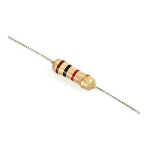
A resistor is a passive electrical component that adds a specific value of resistance to an electric circuit. Resistors are used to reduce current flow, adjust voltages, among others. A resistor functions by converting electrical energy into heat and usually consists of multiple copper wounds. The thickness and length of this copper coil determine the actual value of resistance. Resistors are therefore used in almost all electronic devices and gadgets as they serve to be one of the most fundamental components of electrical circuits.
Power Dissipation
As mentioned earlier, resistors function by dissipating power through the conversion of electrical energy to heat energy. Use the following equation to calculate for power loss:


Determining the power loss of a resistor is also vital as different resistors have different power ratings. If the calculated power loss of a resistor in a circuit is greater than the resistor’s power rating, the resistor is likely to fail due to overheating.
Sample Problem
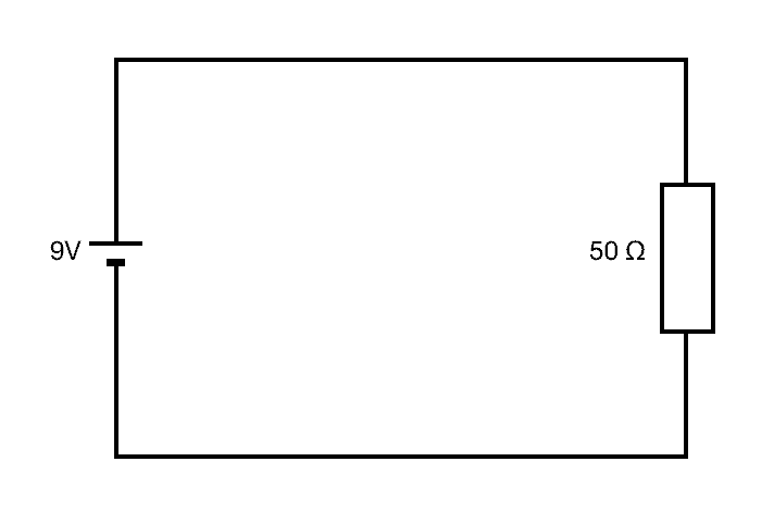
To calculate the power dissipated by the resistor in the circuit above, we need to determine the magnitude of the current that flows through the circuit. This can be calculated using Ohm’s Law where I = V/R. Therefore, 9/50 = 0.18 A. Using the P = IV equation, we get that the power dissipated by the resistor above is 1.62 W. This means that the power rating of the resistor should be greater than 1.62 W to avoid overheating.
Resistors in Circuits
When it comes to setting up resistors in circuits, there are two main configurations: in series or in parallel.
Series Circuit
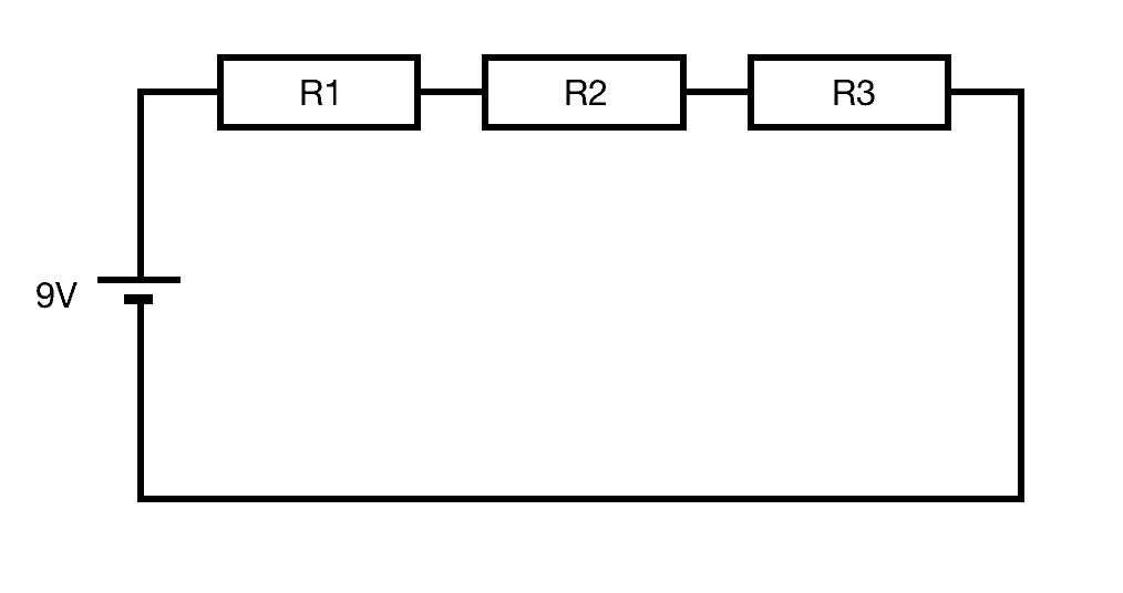
In a series circuit, resistors are lined up one after another. In this configuration, the current throughout the entire circuit stays constant. However, the potential difference between each resistor can vary depending on the value of each resistor.
Use this equation to get the total resistance in a series circuit:

Parallel Circuits
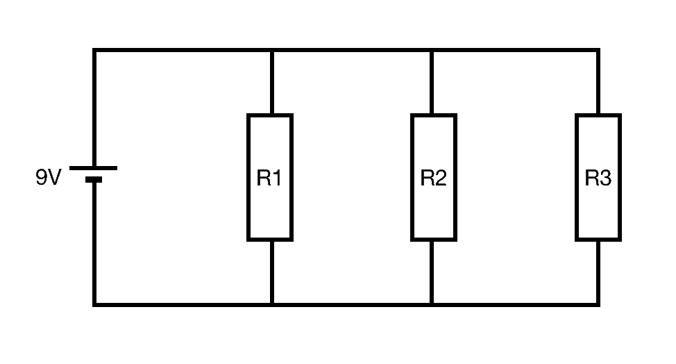
In a parallel circuit, resistors are lined up in a ‘parallel’ fashion one after another. In this configuration, the voltage drop across each resistor remains constant. However, the current across each resistor can vary depending on the value of each resistor.
Use this equation to get the total resistance in a parallel circuit: