What is a Relay?
A relay is an electromagnetic switch that opens and closes circuits electromechanically or electronically. A relatively small electric current that can turn on or off a much larger electric current operates a relay. Relays work like some electrical products since they receive an electrical signal and send the signal to other equipment by turning the switch on and off. Even if the relay contact is normally closed or normally open, they are not energized. Its state will change only if you apply an electrical current to the contacts.

Relays are useful in many applications. Electromagnetic relays protect various AC and DC equipment. It is also used as auxiliary relays in the contact systems of protective relay schemes, for differential protection and the over- or under-current protection of various AC and DC equipment. The current carrier pilot relaying scheme protects transmission lines.
How Relays Work
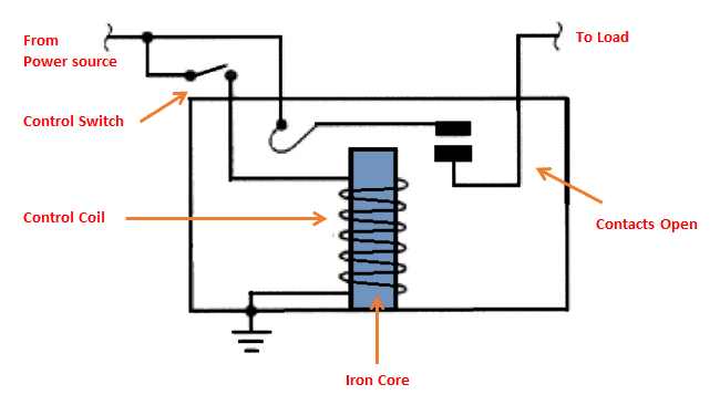
The figure above shows the inner sections diagram of a relay. A control coil surrounds the iron core. The electromagnet starts energizing when the current flows through the control coil then intensifies the magnetic field. The electromagnet becomes connected to the power source through the contacts to the load and a control switch. The upper contact arm becomes attracted to the lower fixed arm and then closes the contacts that result in a short circuit. The contact then moves in the opposite direction and creates an open circuit once the relay has been de-energized.
The movable armature will return to its initial position when the coil current is off. The force that causes its movement will be almost the same as the half strength of the magnetic force. Spring and gravity provide this force.
Relays can operate in two ways. The first is in low voltage application, and the other is in high voltage application. It is used to reduce the noise of the whole circuit in low voltage applications. On the other hand, relays reduce arcing in high voltage applications.
What is inductor flyback?
Inductor flyback is the voltage spike made by an inductor when the power supply is removed or reduced. A voltage spike happens when the current flowing through the inductor is constant. The inductor time constant limits the rate of change of the current just like how the capacitor time constant limits the rate of the voltage change across its terminals.
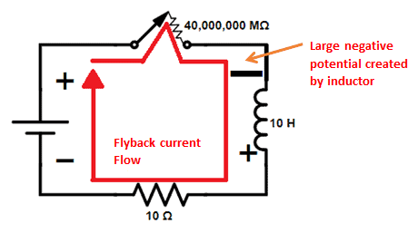
Flyback voltage created by the inductive loads will damage the component used to open and close the circuit. The inductor will find a way to make the current match its dissipation curve. As shown in the figure above, creating a voltage drop across the resistor by switching its polarity will keep the current flowing in the inductor. Energy in the magnetic field is used to make this happen. Current will still not flow at the ideal rate of the inductor even though there is already a voltage drop across the gap resistor. Before the switch was opened the inductor wants the flow of current to be 99%.However, multiplying a small current with such a large resistance will result in huge voltage. As what is showing in the figure, the inductor used the excess of the stored energy to create a huge negative potential on one side of the gap resistor to achieve large voltage drop. Therefore, the current flows according to its dissipation curve.
Why do relays need a transient suppressor?
Relays need a transient suppressor to prevent the possibility of a switching device in the circuit from being destroyed by the inductive flyback. It provides a way for the flow of current once the inductor is disconnected.
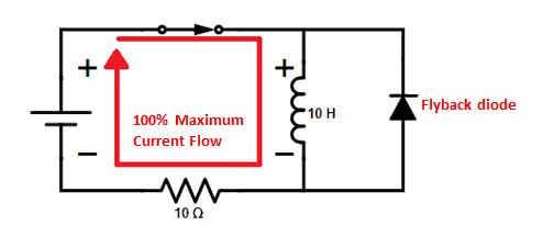
In the figure above, the polarity of the power supply and the diode is opposite to each other. In this way, the diode is in reverse bias whenever the switch is closed. Since it is in reverse bias, it will not affect the circuit because the diode will not allow the flow of current.
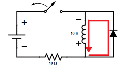
The figure above shows an open circuit where the inductor reversed its polarity, and the diode is in forward bias. In this setup, the diode will allow the flow and dissipation of current at the rate that the inductor wants. The addition of diode gives way to the flow of current. Thus, the inductor only needs to create a small voltage drop to develop the ideal amount of current flow since diodes have almost zero resistance when set in forward bias. With this setup, the switching device will not be damaged. Therefore, when the switch is open, the inductor’s reversed polarity will match the diode’s polarity and prevent the flyback voltage spike.

Normally Open, Normally Closed and Common Terminal
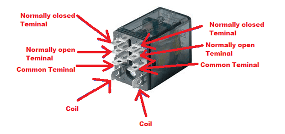
- Normally Open (NO) terminal – connect your device (e.g., LED or any load) to this terminal if you want the device to be off when the relay is not powered, and on when the relay is powered.
- Normally Closed (NC) terminal – connect to this terminal if you want your device to be off when the relay is powered and normally on when the relay is not powered.
- Common Terminal – it is the terminal of the relay where you connect the first part of your circuit. When the relay is powered, and the switch is closed, the common terminal and the normally open terminal have continuity. On the other hand, when the relay is not powered, and the switch is open, the common terminal and the normally closed terminal have continuity.
- COIL – the terminals where you apply voltage to supply power to the coils that will eventually close the switch. Here, polarity is not important. Either of the sides can be negative or positive. However, polarity does matter when using a diode.
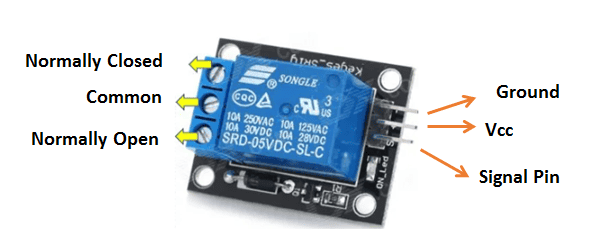
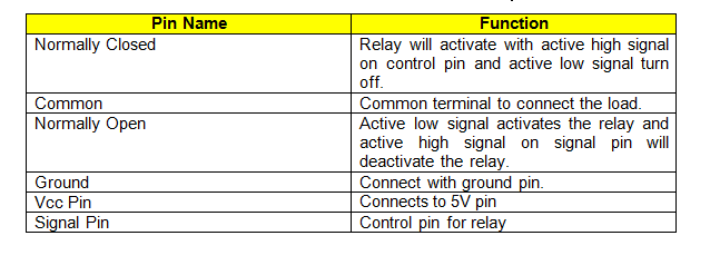
Pins in an SRD-05VDC-SL-C 5V Relay
Sample Schematic using SRD-05VDC-SL-C 5V Relay
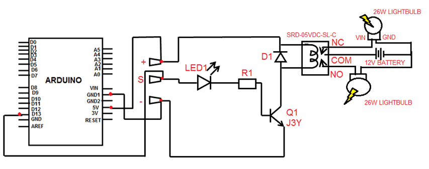
The S pin connection is the input. The + pin connects to a +5V DC power supply while the – pin connects to the power supply ground. The relay and LED will operate when a high signal is present on the S input. The diode across the relay coil is there to prevent emf from the coil. The transistor provides current gain, and a small input current can switch the relatively large current need to operate the relay coil. You can connect the S input of the relay board to any of the Arduino Uno digital outputs. In this case, it is connected to pin 13, which can be turned on and off. The light bulb and a 12V battery are connected in series to the common terminal and normally open pin contacts on the relay module. The relay will work and turn on the lightbulb when the output from the Arduino is high. Adding another light bulb to the normally closed pin contact of the relay will then make alternate flashing light bulbs.