What are Power Inverters?
A power inverter is a device to convert a battery DC supply—typically 12V—to an AC supply, typically 220V at 50Hz, or, in some countries, to 110V at 60Hz.
They come in various power output levels from as little as 100VA to several kVA. The limit in size, weight, and cost is inevitably the required batteries, which are generally lead-acid for a reduced cost. People use inverters wherever standby mains are needed in outages or where there may not be mains available. We also use them when energy is being derived from solar or wind power.
An inverter would be an important part of an un-uninterrupted power supply (UPS).
How Power Inverters Work
Inverters range from simple homemade ones to very elaborate ones. The homemade are those with a few transistors and a scrap mains transformer. Elaborate ones are those with microcontrollers generating PWM sine waves and sophisticated protection circuits.
We will look at the simplest type and build one to see how it works.
In a commercial one, if it was rated at 100VA output and say 110V, you would expect the output current to be 100/110 = 0.9A. Assuming an efficiency of 80%, there would be more than 100VA going in, or about 10A.
I must caution you though. This project will involve work at mains and, therefore, lethal voltages. Projects like these should only be taken on by suitably trained folks who understand the danger.
How to Build an Inverter

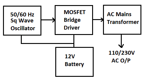
Above is the block diagram of the inverter we are going to make.
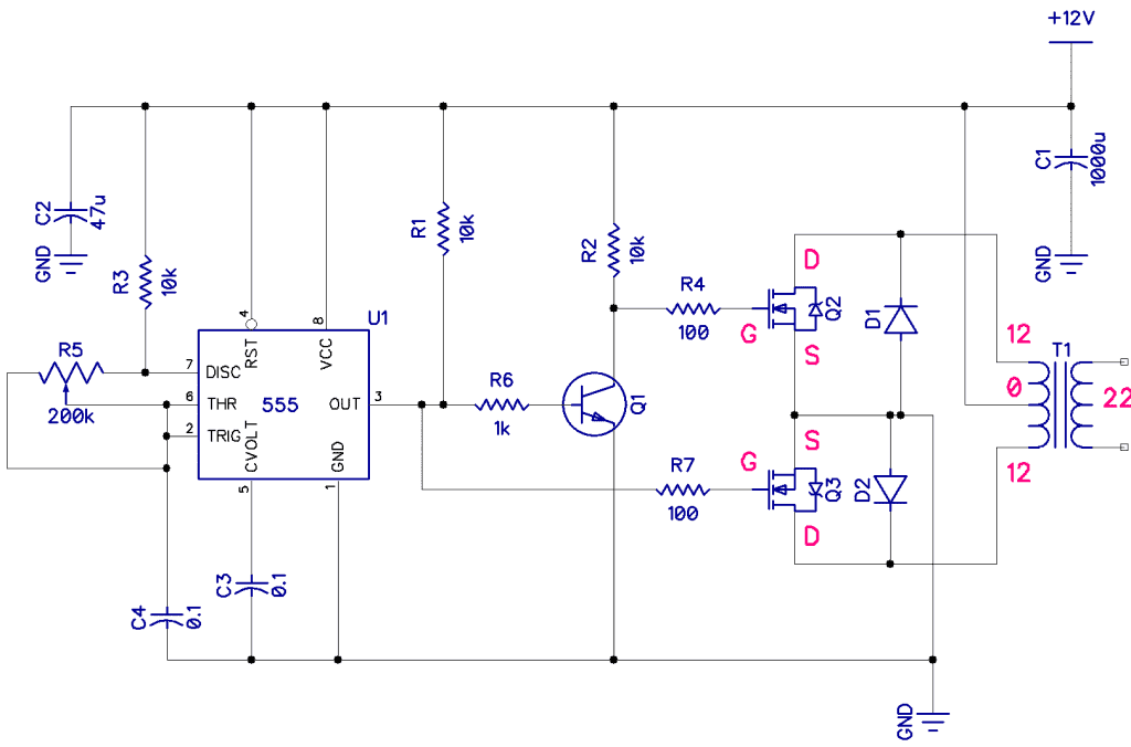
The 50Hz oscillator is based on a 555 timer providing a 50Hz square wave and an inverting transistor to give a 180º phase shift. Now, we have two outputs to drive the bridge. The frequency is controlled by the pot between pins 6 and 7, which can be set to 50 or 60Hz.
A half-bridge MOSFET circuit follows this turned fully on and fully off by the square wave on their gates. This is quite important as we do not want the MOSFETs to be in any partly ‘linear’ state as this will dissipate much power and heat. Since they have a very low internal resistance, they are not dissipating power when hard-on.
The drains are connected to the 12/0/12 side of the mains transformer. Since this is an inductive load, we will have two flyback diodes to prevent a back emf spike from killing the MOSFETs
The poor mains transformer is a conventional PSU transformer and was never intended to be working with a square wave input. However, it still works and steps up the 12V to near the original 220V primary. If you are in a country where you normally use 110V, you can use a 12/0/12 to 110 transformer. You can add a 47nF across the output to kill radiated harmonics of the square wave, and this also serves to round off the shape of the output a bit. This can also be improved with a low pass filter consisting of a series inductance and a parallel capacitor.
The size of the mains transformer and the amount of current that can be drawn from the battery will govern how much AC power is available. But in general, if you have a 100VA transformer, then you should be able to get close to 100/110v = 0.9A.
I say close because the efficiency is about 70%, so this will reduce to about 0.6A. This will be more than enough to run a cell phone charger or a few LED lights.
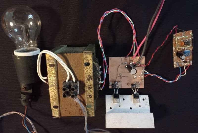
In the lash-up of mine, I had 12V at 4.5A going in and about 190V coming out, driving a 60W globe fairly brightly. So while one can not measure the current properly as it is a square wave, it appeared to be pretty efficient. A higher output voltage could be reached, possibly with a 10/0/10V transformer, but I had to use what I had.

You could use it by putting a mains socket on the output, but as I said before, this thing can bite you if you are not careful!
What a Working Inverter Circuit Looks Like


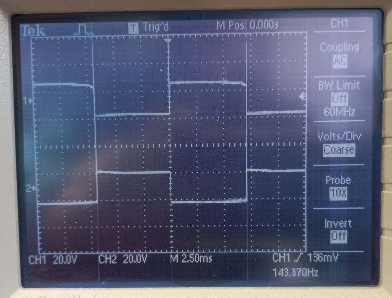
Shown below are the waveforms at the gates of the MOSFETs. Note that they are 180º out of phase. And next to that is the output high-voltage waveform. I was using a 100X probe to measure the output.


The circuit worked quite nicely. I found that the MOSFETs need to be low Rds types such as IRF540 or IRLZ44 and that we need a heat sink. We could set the 555 over a wide range of frequencies, and the circuit will still work quite happily at 200H!
Q1 is any transistor such as A BC337 or BC237, and the diodes are 1N4004. I would avoid trying to drive and fancy devices without some filtering as the waveform is very square, but things like chargers, etc. will be fine.


