What are Flip Flops?
Flip flops are essential in data storage. They are electronic circuits with two stable states used to store binary data. Such a circuit has one or more control inputs and one or two outputs. By applying varying input, the data stored can be changed. In sequential logic, the flip flop is the basic storage element. They are fundamental building blocks of electronics systems such as computers and communication devices.

A flip flop stores a single bit or binary digit of data. The two states of a flip flop represent “one” and “zero.” The output and the next state of a flip flop depend on its current input and current state when used in a finite-state machine. Used for counting of pulses and synchronizing variably-timed input signals to some reference timing signal, a flip flop can be level-triggered or edge-triggered. Level-triggered flip flops can be asynchronous, transparent, or opaque, while edge-triggered flip flops can be synchronous or clocked.
Flip flops are related to clocked devices or clocking. Clocked devices ignore their inputs except at the transition of a dedicated clock signal. A flip flop either change or retain its output signal based on the values of the input signals at the transition caused by clocking. Some flip flops change the output on the rising edge of the clock, others on the falling edge. Since the elementary amplifying stages are inverting, two stages can be connected in cascade to form the needed non-inverting amplifier.
Common and Practical Uses of Flip Flops
A flip flop has many possible uses. In digital electronics, edge-triggered flip flops are used as a main component for sequential circuits. Among its uses is storing or transferring binary data from a certain location to another and as a counter. Some applications make use of the flip flop’s clocked operation, and such applications fall under the category of sequential circuits. Flip flops are seen in counters, storage registers, shift registers, frequency divider circuits, and data transfer.
Counters
These electronic devices are widely used in electronics especially in digital systems. Counters count the number of a specific event occurring in a specific interval of time. Because counters remember past states, they need to have a memory and use flip flops for this purpose. Counters could be synchronous or asynchronous. For synchronous counters, flip flops are connected to the same clock signal. These flip flops will then trigger at the same time. For asynchronous counters, flip flops are connected and complemented together.
Registers
As mentioned earlier, flip flops store single bits of data; either “one” or zero”. On the other hand, registers are used to store multiple bits of data. But as such, flip flops are used to design registers.
Data Transfer
This is the process of transferring data from one register to another. Nowadays, data can be transferred using flip flops.
Types of Flip Flops
There are four common types of flip flops.
SR Flip Flop
An SR flip flop is similar to SR latches. This type of flip flop has two inputs; SET and RESET, and a CLOCK input. When the clock is triggered, the Q output goes high if the SET input is high. On the other hand, the Q output goes low if the RESET input is high. Remember that SR flip flops have two inputs; the SET and the RESET, and should not be set to high when the clock is triggered. This type of flip flop operates only with positive clock transitions or negative clock transitions.
JK Flip Flop
The modified version of an SR flip flop, the JK flip flop, operates only with positive clock transitions or negative clock transitions. This type of flip flop has two inputs; J and K. The J input of a JK flip flop is like the SET input of an SR flip flop. Likewise, the K input of a JK flip flop is like the RESET input of an SR flip flop. In an SR flip flop, the SET and the RESET inputs cannot be both high. In a JK flip flop, both the J and K inputs can be high. When that happens, the Q input is toggled, meaning the output alternates between high and low.

D Flip Flop
Aside from the CLOCK input, a D flip flop has only one additional input—the DATA input. The Q output goes high if the DATA input is high. The Q output is low if the DATA input is low. This type of flip flop operates only with positive clock transitions or negative clock transitions. The D is also known as delay because this type of flip flop transfers its data between the input and its outputs after a delay of one clock pulse. Most D flip flops include S and R inputs allowing you to set or reset the flip flop.
T Flip Flop
This type of flip flop is not commercially available. However, you can make one out of a JK flip flop or a D flip flop. This is similar to a JK flip flop—the output alternates between high and low with each clock pulse. Toggles are combined to form a counting circuit. The current state of the Q output is inverted when a clock pulse is received. This is then fed back to the D input. Such operation causes the output to alternate between high and low. As mentioned above, when the J and K inputs are high, the JK flip flop acts as a toggle.
Popular Flip Flop IC (CD4013 Dual D-type Flip Flop)
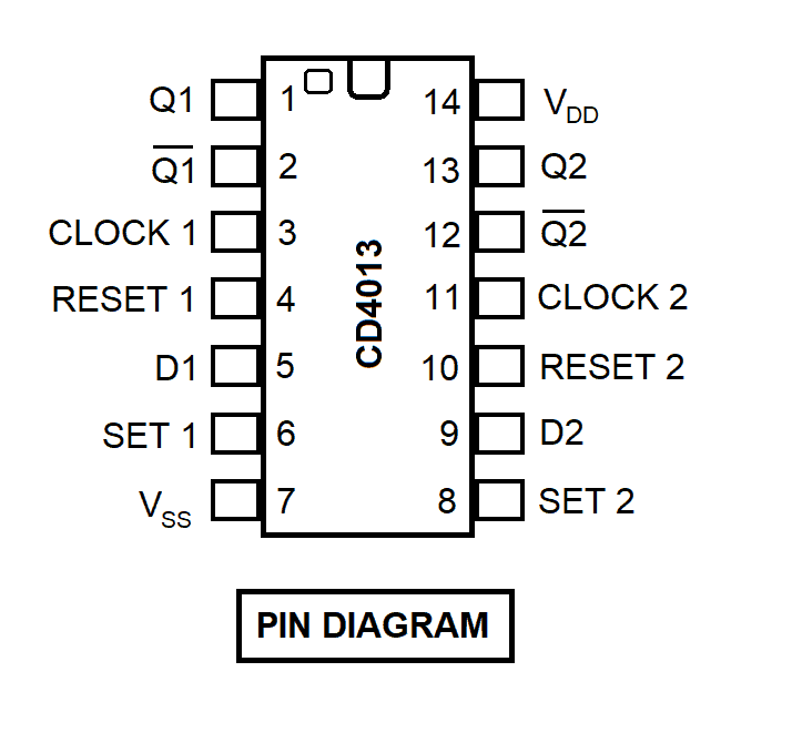
The CD4013 Dual D-Flip Flop IC has two identical and independent data type flip flops. Because they are independent, each of the data type flip flops has its set input, reset input, clock input, and Q outputs. This integrated circuit could be used for control circuits, registers, counters, and more. Regardless of the levels of the other inputs, a high level at the set input or reset input will set or reset the outputs. And whenever the set input and the reset input are low or inactive, the output will show the data at the input at the time of the last low-to-high clock transition. This will then be held until the next transition. Clock triggering occurs at a voltage level and it is not related directly to the rise time of the clock pulse. The positive power supply, which is pin 14, should range from 3V to 16V. Pin 7 is the ground.
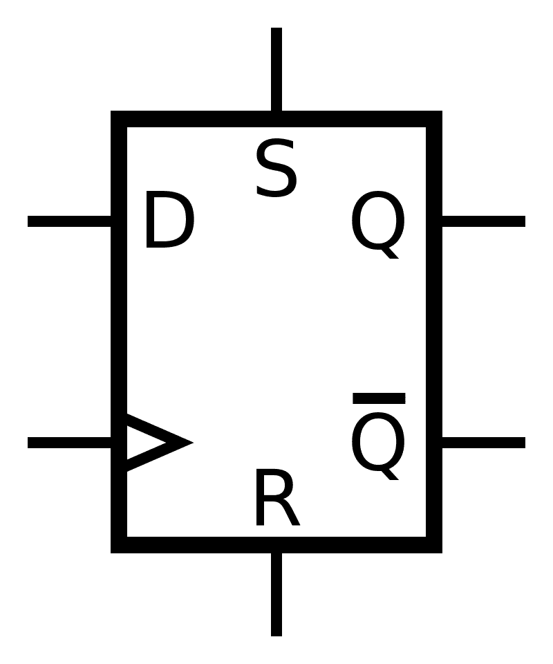
Below is the schematic symbol of a D-flip flop.
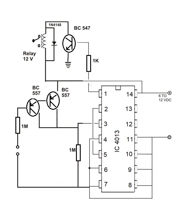
Sample Schematic Using a Flip Flop