Pulse Width Modulation
Pulse Width Modulation, or PWM, is a digital technique to enable the proportional control of analog devices more efficiently. It generates variable-width pulses to represent the amplitude of an analog input signal. The output switching transistor is on more of the time for a high-amplitude signal and off more of the time for a low-amplitude signal. The digital nature (fully on or off) of a PWM circuit is less costly to fabricate than an analog circuit that does not drift over time. Typical devices using this are DC motors, heaters, lights, LEDs, hybrid car motors, ovens, kilns, fans, etc.

How it works
In the past, such devices might have been controlled by a simple inline resistor. But according to Ohm’s law, this would create a great deal of heat across the resistor. So a train of pulses at a moderately high frequency is applied to the device through a suitable drive transistor or power MOSFET in a digital system. Now, because the drive is either fully on or fully off, there is no I2R loss across the device (in reality, the MOSFET might have a small on-resistance of a few milliohms).
If the driver is on half the time and off half the time, it would make sense that the average power in the heater is only half or 50%. If the ratio of on to off is variable, any degree of control can be obtained.
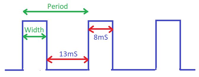
In the figure above, we see that the pulse is on for 8mS and off for 13mS. The period is the sum of the two, which is 8+13 = 21mS. The frequency is the inverse of the Period, which is 1/21mS = 47.6Hz. The duty cycle or mark-to-space ratio is (width÷period) * 100 = (8/21) * 100 = 38%.
If the pulse voltage was 5V, the average DC voltage would be duty cycle*V = (38/100) * 5 = 1.9V.
Sample Circuit
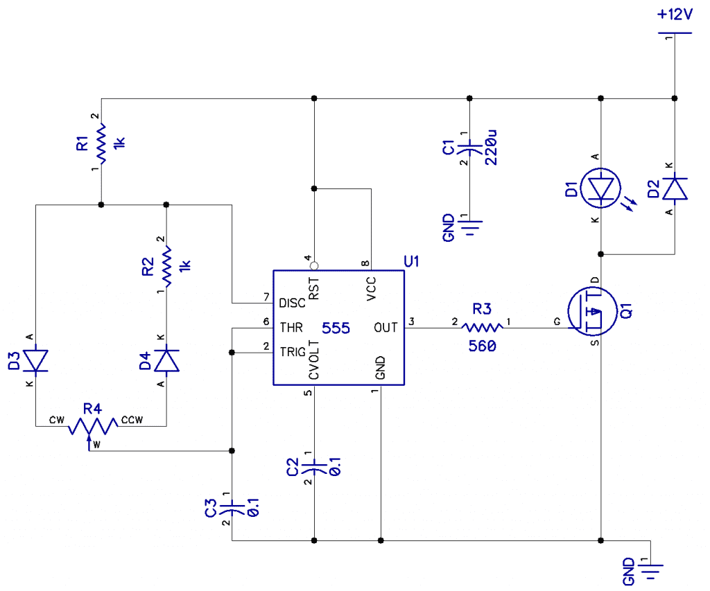
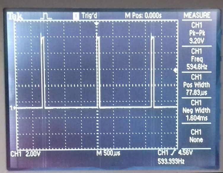
In the circuit above, we see a 555 wired as a PWM astable oscillator. Q1 is a MOSFET, an IRF540 is fine, and D1 is a LED (or, for example, a small DC motor). D2 prevents any back EMF from an inductive load (if the LED was a motor instead) from damaging the MOSFET. The frequency is fixed and is a function of R1, 2, and 4 with C3 and is about 595Hz. R4 (about 20k) adjusts the duty cycle, and as you can see from the two oscilloscope displays below, this is from 78uS to 1.6mS. Like before, period is 78+1600us = 1678uS and frequency is 1/P = 596Hz.
Working out the duty cycle in example 1, (width÷period) * 100 = (77.9÷1678)*100 = 4.6%, and in example 2, (1570÷1678)*100 = 93.5%.
So you can see, we can dim the LED D1 very nicely, or control the speed of a small motor.
If you were to go right down to 0%, you would have a straight line at the bottom of the trace at 0v and 100% the same but at 5V.
A good question to ask at this point would be, given any duty cycle, what effect does frequency have? Actually, none. However, if the frequency is too low, you will get visible flickering on the LED, and if too high, the control device or the load will not be able to turn on and off fast enough.

 |
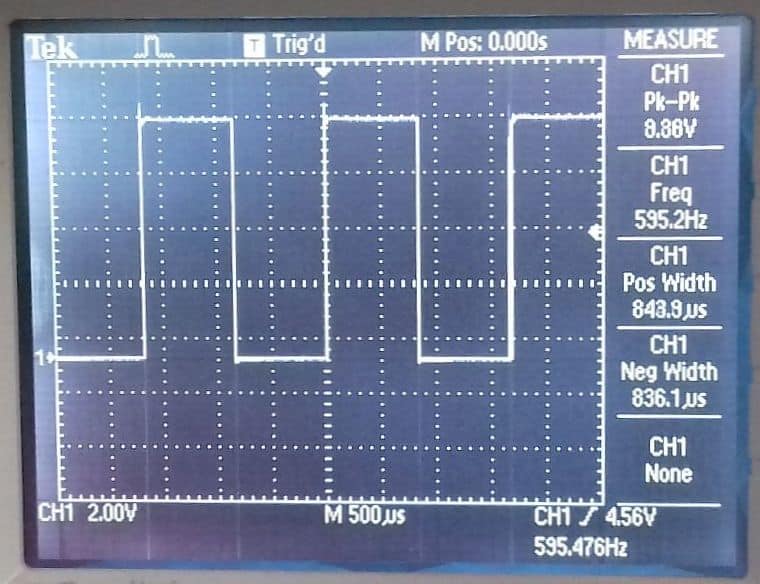 |
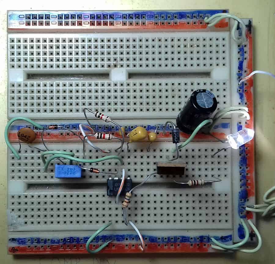
| Breadboard of the above circuit | A 50% duty cycle |
 |
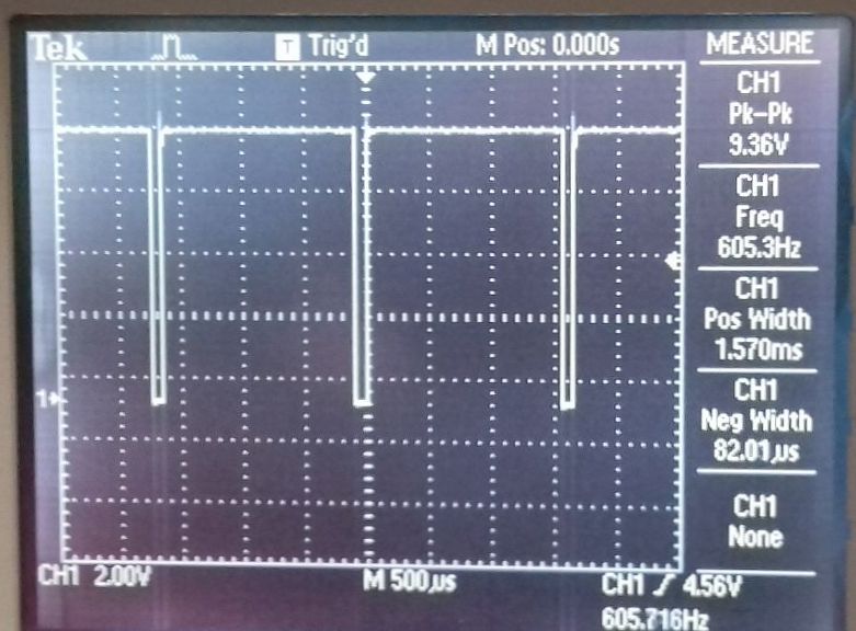 |
| 4.6% Duty Cycle | 93.5% Duty Cycle |
We have seen a simple 555 astable oscillator controlling an LED. Many microcontrollers, such as the Arduino, have a PWM function built-in to make it easy to control a device. Note that not all the pins can do PWM. The UNO, for example, can only do PWM on 3, 5, 6, 9, 10, and 11. The PWM signal frequency on pins 5 and 6 will be about 980Hz, and on other pins will be 490Hz.