Protection Circuits
All electronic devices need protection circuits. They are used, as the name implies, to protect either the power supply from being forced to deliver excessive current into overload or short circuit or to protect the connected circuit from a reverse connected power supply or a voltage that exceeds the circuit design voltage. They can be classified as follows:
Overvoltage Protection
A “crowbar” circuit (shown in Figure 1) can protect your device from overvoltage. In normal use, the 12V supply goes to the output via the reverse protection diode and fuse. The Zener is chosen to be slightly higher; in this case, 15V. When the input voltage reaches 15V, the Zener conducts, setting up a voltage across R2. When this reaches the trigger voltage of the SCR (less than 1V), the SCR fires, creating a short circuit across the input, which causes the fuse to blow. C1 ensures spikes caused by switching transients don’t trigger the SCR. The SCR and Zener must be able to handle the sudden inrush current until the fuse blows.
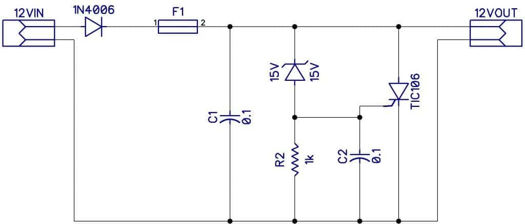
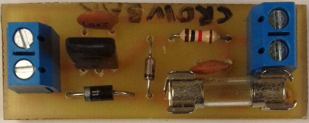
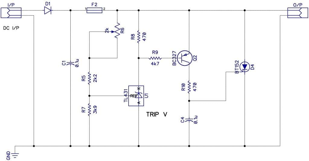
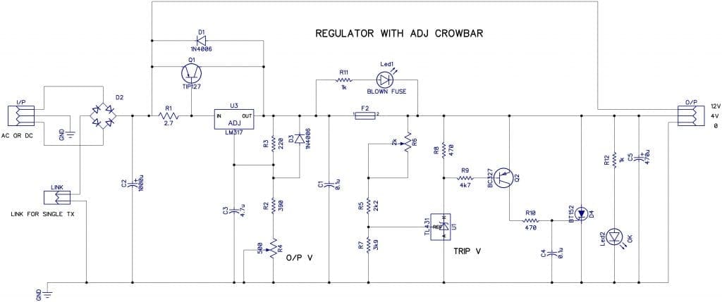
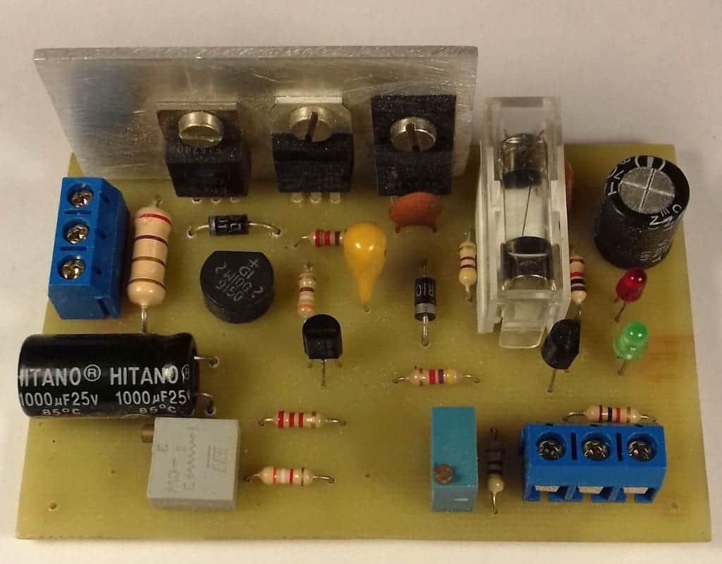
Figure 2 shows almost the same circuit except the Zener has been replaced with a programmable Zener D5. By varying the voltage at its input with R6, you can set the trigger voltage, providing a lot more flexibility. Finally, Figure 3 shows the same circuit added to a voltage regulator and a blown fuse indicator and a picture of the completed project.
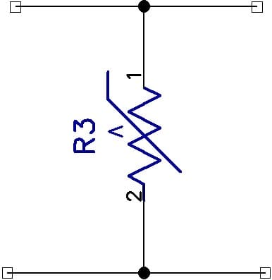
Another form of overvoltage that occurs is a transient spike on the power line. These are more likely to be a problem at the mains end of the AC power supply. A solution often used is to put MOVs across the supply. An MOV (metal oxide variable) is like a high-value resistor (several hundred K), which reacts very quickly to an increase in voltage. For the duration of the transient drops, its resistance is low enough to shun out the spike. See Figure 4 below.
Overcurrent Protection
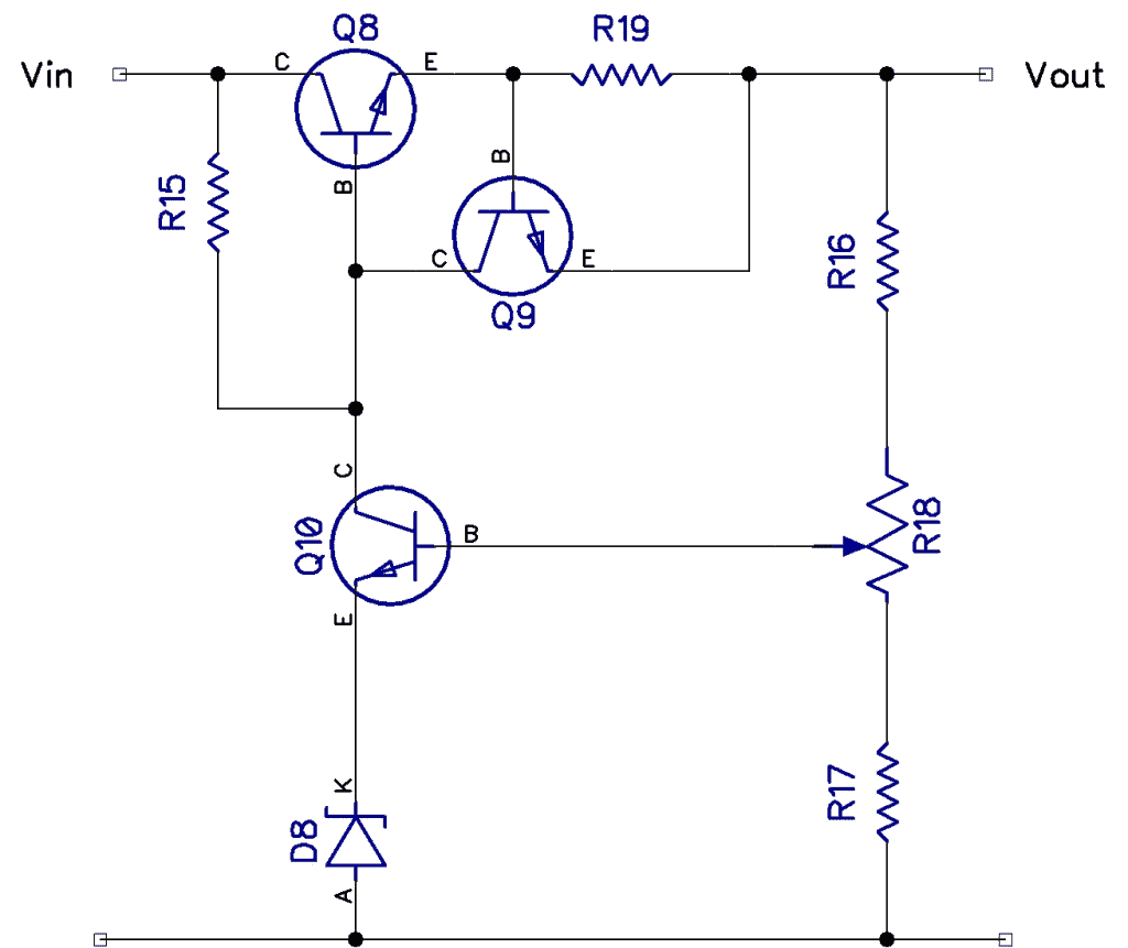
In a previous article, we looked at regulators and how to limit its current. Let’s take a second look at it now.
Other Overcurrent Protection
Of course, there are other overcurrent devices such as fuses and circuit breakers for larger AC currents, perhaps in your home electricity supply.
Circuit breakers are a topic on their own. But simply put, they are simple switches which have a mechanism to trip them. In a conventional circuit breaker, this is a bi-metal strip through which the current flows and bends as it heats up. It is then mechanically attached to the trip mechanism and trips at a certain current. Circuit breakers also have a small inductive component, so the breaker can be made to trip slowly on overload or very fast on a short circuit. Here is a great video showing slow-motion tripping.
Reverse Polarity Protection
Reverse polarity protection is the easiest to achieve. A simple diode in the path of the incoming power will do. But this needs to have an appropriate current rating. In Figure 6, the 1N4006 has a 1A rated current and PIV (peak reverse voltage) of 800V, so this should suffice for most projects. The diode will cause a constant volt drop of 0.6 to 0.7V, but this should not be a problem. However, if you have a circuit that needs to work at a very low voltage, the 0.6V drop across the series diode could be a problem. In this case, Figure 6 (right-hand side) shows a shunt diode.


Back EMF Reverse Polarity Protection
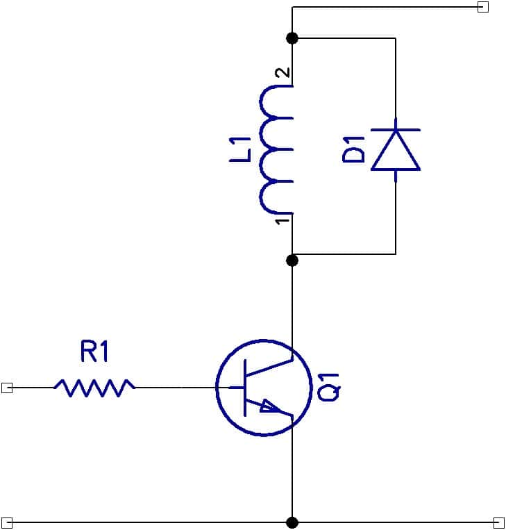
There is another form of reverse polarity that occurs when you are not expecting it. Anytime an inductance carrying current is switched off, the stored magnetic field in the inductor needs to collapse, and it will try to do this backward across its terminals. Not only that, it may be hundreds of volts. (This is how old-style auto spark plugs work.) You can also protect your device from this back EMF using a reversed diode across the inductance, as shown in figure 7. Note that the diode should have a high PIV rating, and a 1N4006 will be adequate.

Lastly, remember that fuses are slow-acting. There’s once a joke that says a $50 transistor will often blow first to protect a 10 cent fuse!


