How to Use Buzzers With Raspberry Pi
Buzzers are often used in DIY devices to create simple sounds for alarms, alerts, and so on. In this tutorial, you will learn how to interface passive and active buzzers with a Raspberry Pi.

Introduction
An active buzzer uses an internal oscillator to generate a tone. This means you only need DC voltage to create a stable sound. They have uneven legs like capacitors. The longer pin indicates the positive terminal of the buzzer. Furthermore, active buzzers have coated bottoms to protect their internal circuitry from fine dust and accidental short circuit.
On the other hand, passive buzzers don’t have internal oscillators. It would help if you had a pulsating AC signal to generate a stable tone. Without this pulsating signal, passive buzzers only produce a clicking sound (the same sound you hear when a relay is triggered). The bad news is microcontrollers and SBCs (Single-Board Computers) can only take DC. You need to emulate the pulsating characteristic of AC to the DC output of the electronics board. You can either tweak the code or create a separate oscillator circuit for the buzzer to produce this signal. Code-wise, you can send low and high signals at great speed to create a signal similar to AC. You can try this using Arduino by using digitalWrite to turn on and off the buzzer every short while, say 100ms. You can also use PWM to trigger the buzzer. You can also use third-party libraries that support this function, both with Arduino and the Raspberry Pi. Visually, passive buzzers have open bottoms and even legs, unlike active buzzers.
Passive buzzers are best when your project requires precise tone and volume control and doesn’t mind adding additional circuitry or code. Active buzzers are best for simple sound generation for alerts and alarms – devices that only produce noise, not music.
In this tutorial, we will use both buzzers to create two different buzzer applications with the Raspberry Pi: an active buzzer as a sound alert when a thermistor reading goes above a certain temperature and a passive buzzer that plays a musical tune.
Using an Active Buzzer
Setup
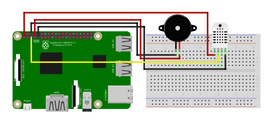
For our first example, we will use an active buzzer as a sound alert when a thermistor reading goes above a certain temperature. The things we need are:
- Raspberry Pi
- Breadboard
- Jumper Wires
- DHT Temperature Sensor
- Active Buzzer
Build the actual circuit following the image below.
We will use the Adafruit DHT Python library to interface our DHT sensor to the Raspberry Pi. You can install it easily with the one-liner code below—no need to install git and other third-party software.
sudo pip3 install Adafruit_DHTCode
Copy the code below to your code editor.
import Adafruit_DHT as AdaDHT
import RPi.GPIO as GPIO DHTSensor = AdaDHT.DHT11
DHTPin = 3
BuzzerPin = 4 GPIO.setwarnings(False)
GPIO.setmode(GPIO.BCM)
GPIO.setup(BuzzerPin, GPIO.OUT, initial=GPIO.LOW) while True: humidity, temperature = AdaDHT.read_retry(DHTSensor, DHTPin) if humidity is not None and temperature is not None: print("Temperature={0:0.1f}*C Humidity={1:0.1f}%".format(temperature,humidity)) if(temperature>32): GPIO.output(DHTPin, GPIO.HIGH) else: GPIO.output(DHTPin, GPIO.LOW) else: print("Failed to retrieve data from sensor")
We only need two python libraries for this project—first, the Adafruit_DHT library to interface with the sensor and the RPi.GPIO library to trigger the buzzer. For the initial setup, we indicate the actual DHT sensor we will use (in my case, DHT11). If you’re using an AM3102 or a DHT22, replace DHT11 on line 4. Next, set the pin numbers for both the sensor and buzzer. I prefer to set the GPIO pin numbering to BCM, but if you’re more comfortable with Board numbering, you can change line 9. Finally. we set the Buzzer pin as an output with an initial LOW state.

The main loop reads the temperature and humidity value from the sensor, and if the readings are valid, print them on the terminal. If the temperature value exceeds 32 degrees Celsius, the Pi will send a HIGH signal to trigger the active buzzer.
Using a Passive Buzzer
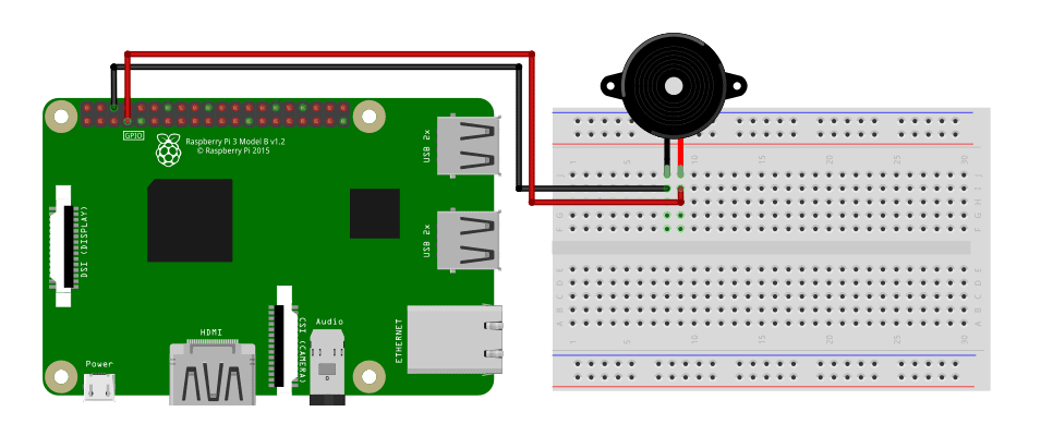
For the next example, we are going use a passive buzzer to play a tune. The things we need are:
- Raspberry Pi
- Breadboard
- Jumper Wires
- Passive Buzzer
Gather all the items and build the circuit as shown below.
Code
Copy the code below to your code editor.
import RPi.GPIO as GPIO
import time BuzzerPin = 4 GPIO.setmode(GPIO.BCM)
GPIO.setup(BuzzerPin, GPIO.OUT) GPIO.setwarnings(False) global Buzz Buzz = GPIO.PWM(BuzzerPin, 440) Buzz.start(50) B0=31
C1=33
CS1=35
D1=37
DS1=39
E1=41
F1=44
FS1=46
G1=49
GS1=52
A1=55
AS1=58
B1=62
C2=65
CS2=69
D2=73
DS2=78
E2=82
F2=87
FS2=93
G2=98
GS2=104
A2=110
AS2=117
B2=123
C3=131
CS3=139
D3=147
DS3=156
E3=165
F3=175
FS3=185
G3=196
GS3=208
A3=220
AS3=233
B3=247
C4=262
CS4=277
D4=294
DS4=311
E4=330
F4=349
FS4=370
G4=392
GS4=415
A4=440
AS4=466
B4=494
C5=523
CS5=554
D5=587
DS5=622
E5=659
F5=698
FS5=740
G5=784
GS5=831
A5=880
AS5=932
B5=988
C6=1047
CS6=1109
D6=1175
DS6=1245
E6=1319
F6=1397
FS6=1480
G6=1568
GS6=1661
A6=1760
AS6=1865
B6=1976
C7=2093
CS7=2217
D7=2349
DS7=2489
E7=2637
F7=2794
FS7=2960
G7=3136
GS7=3322
A7=3520
AS7=3729
B7=3951
C8=4186
CS8=4435
D8=4699
DS8=4978 song = [ G4, E4, F4, G4, G4, G4, A4, B4, C5, C5, C5, E4, F4, G4, G4, G4, A4, G4, F4, F4, E4, G4, C4, E4, D4, F4, B3, C4
] beat = [ 8, 8, 8, 4, 4, 4, 8, 8, 4, 4, 4, 8, 8, 4, 4, 4, 8, 8, 4, 2, 4, 4, 4, 4, 4, 2, 4, 1
] while True: for i in range(1, len(song)): Buzz.ChangeFrequency(song[i]) time.sleep(beat[i]*0.13)
We will use two Python libraries as well with this example project.
First, use the RPi.GPIO library to trigger the Buzzer, then the time library to space out the melody’s notes. For the initial setup, we will define the buzzer pin and the pin numbering system to BCM. We will initialize the PWM as the variable Buzz and set the duty ratio to 50%. Next, we define all the possible notes we can use to compose a tune by their frequency. The song I used for this example is “Santa Claus is Coming to Town.”
To build the tune, we indicate the notes of the song paired with the beats. These beats are the spacings between notes. In the main loop, every note is sent to the passive buzzer using PWM. Then, the Pi will rest for silence according to the respective beat value. You can set the tempo with a constant multiplier.