OR Gate – Logic Gates Tutorial
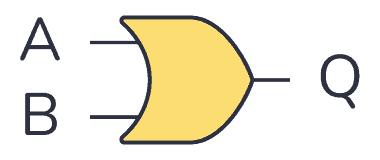
An OR gate is a logic gate where the output goes HIGH (or “1”) if any of its inputs are HIGH. So if A OR B is HIGH, the output Q also becomes HIGH.

The logic or Boolean expression for an OR gate is  which means:
If A or B is true, then Q is true
Truth Table
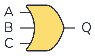
OR gates can have more than two inputs. But no matter how many inputs it has, it will always give out a HIGH or logic “1” if one of its inputs is HIGH.
2-input OR Gate Truth Table
| Input A | Input B | Output Q |
|---|---|---|
| 0 | 0 | 0 |
| 0 | 1 | 1 |
| 1 | 0 | 1 |
| 1 | 1 | 1 |
3-input OR Gate Truth Table
| Input A | Input B | Input C | Output Q |
|---|---|---|---|
| 0 | 0 | 0 | 0 |
| 0 | 0 | 1 | 1 |
| 0 | 1 | 0 | 1 |
| 0 | 1 | 1 | 1 |
| 1 | 0 | 0 | 1 |
| 1 | 0 | 1 | 1 |
| 1 | 1 | 0 | 1 |
| 1 | 1 | 1 | 1 |
IC Alternatives with OR Gates
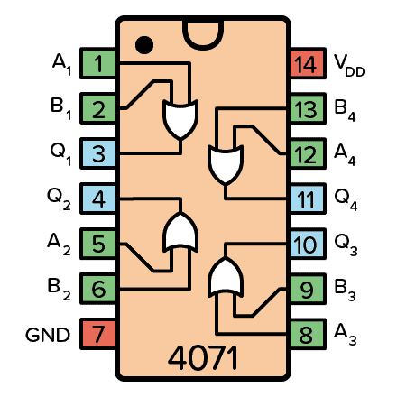
If you want to experiment and build circuits with OR gates, you’ll find them in both the 4000 IC series and the 7400 IC series:
- 4071: Four 2-input OR gates
- 4075: Three 3-input OR gates
- 74HC32: Four 2-input OR gates (HC is the family, can also be LS/HCT/…)
- 74HC4075: Three 3-input OR gates (HC is the family, can also be LS/HCT/…)
These should all be available as hobbyist-friendly through-hole chips. Just make sure you buy the DIP package version.
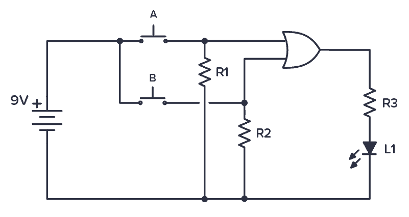
Example Circuit: Testing an OR gate
Below is a simple practical circuit you can build to test how this gate works. A Light-Emitting Diode (LED) turns on when you press either of the buttons A OR B. The circuit demonstrates the basic operation of an OR gate.
Next Step in the Logic Gates Tutorial
Check out the other articles in this logic gates tutorial:
NOT Gate/Inverter
AND Gate
NAND Gate
OR Gate – (You are here)
NOR Gate
XOR Gate
XNOR Gate